The impeller of a typical axial flow pump and the flow through a radial flow pump are shown in the illustration below. Determination of the main dimensions of the impeller 3.

Energies Free Full Text Multi Disciplinary Optimization Design Of Axial Flow Pump Impellers Based On The Approximation Model Html
However one-dimensional flow theory which is based on Euler equations is convenient and simple.

. This enables a single speed axial fan to be capable of a wide range of duties. The axial flow pump includes the impeller rotating inside a casing of sufficient length and that ensures uniform incoming and outgoing flow. For design calculation the design parameters are taken as follows.
Axial Flow Pumps. The main parameters of the axial flow pump hydraulic model are as follows. Guide vanes are used to control airflow and fan static pressure.
Total flow PrimaryEntrained is often considered to be 25 to 3 times greater. Feasibility check of the input parameters. Some designs of axial impellers allow the angle of the blades to be adjusted either while stationary or in motion.
6 Volume flow through impeller eye 7 Air horsepower 7hp overall 70 8 Brake horse power 9 Torque T Torque T 182608 lb-in Allowed shear stress 10 Shaft diameterd 15 in The shaft diameter D s is based upon the critical speed and deflection. Hub and tip diameter at inlet and outlet. The method allows a mathematical description of the skeleton line as a parabola taking into account the entrance and exit angles of the blade.
N1 is the rotational velocity of impeller. But this design was not successful due to a tendency of the gas to coalesce at the top of the vessel and because there was a general lack of knowledge. So the design data are required to design the centrifugal pump.
Finding the mean meridian flow hull and generating mean line blading. Head H 10 m. An investigation in to usage of new materials is required.
Impeller is designed on the basic of design flow rate pump head and pump specific speed. For design calculation the design parameters are taken as follows. This study relates to the impeller design of axial flow pump that can develop a head of 3 m and deliver 03 m3s of water at the speed of 1000 rpm.
Application of internal or user-defined approximation functions for defining impeller parameters. Flow rate Q 1000 m3hour Head H 8 m Pump speed n 1400 rpm Gravitational acceleration g 981 ms2 Density of. Hub must not have axial parts within blade area.
So the design data are required to design the centrifugal pump. Guide vanes can be upstream or downstream from impeller. Hub must overlap shroud in z-direction about 50 or more.
Engineers coming from home and abroad factories widely employ one-dimensional flow theory to optimally design an impeller for a centrifugal pump 9 11. The objective of this paper is to be design the impeller for a centrifugal caustic slurry pump to increase its power and efficiency and showing the advantage of designing parameters six blade turbine design changes from impeller comparing with the old material of a TURBINE. Axial impellers only.
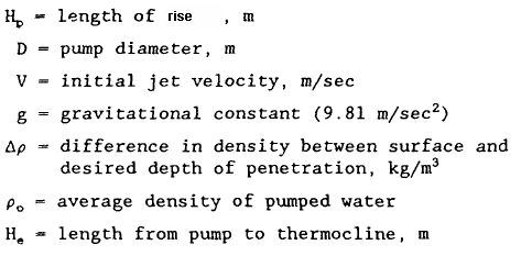
For use as a design factor Equation I can be used to solve for the design velocity assuming a. Design Calculation of Impeller for Axial Flow Pump. N2 is another rotational velocity of the impeller.
Impeller diameter D 300 mm impeller inlet radius r 1 14697 mm. At first the pitched-blade turbine Figure 2 was used as an upper impeller. End users began to experiment with impeller systems that combined axial and radial impellers.
The hydraulic model of the axial flow pump selected for this experiment is shown in Fig. Up to 10 cash back details. Axial fan impellers rotate at a higher blade tip speed than a centrifugal fan of similar performance and hence tend to be noisier.
In order to improve the airflow efficiency of a fan you need to minimise the losses Lˢ Lᶠ Lᵉ and to do this you need to optimise the size and shape of the its blades. Axial Centrifugal Blade Design This calculation option determines the airflow through impeller blades. The axial flow pump impeller all-operating-condition design method adopts CFD numerical calculation the design accuray is high and optimization results are reliable.
Available only if the meridional direction is mainly radial. High noise levels and high initial cost of vane axial fans with variable vane guides make it uneconomical comparing to variable speed motors. Thus the impeller forces the liquid into a rotary motion by impeller action.
Two alternative design modes. Airfoil hydrofoil design or mean line design. The equation below calculates the Primary pumping capacity of one impeller and does NOT include entrained flow.
An axial flow pump impeller all-operating-condition design method comprises the following steps that 1 parametric modeling of an axial flow pump impeller is performed namely 2k design parameters including. Impellers can be designed to impart various flow characteristics to pump or tank media. These velocities are directly proportional to the fan flow volume.
Qu1 is the volume flow at rotational velocity n1. Input fluid properties inlet conditions and main stage parameters. An analytic method for designing blades of the impeller of an axial dredge pump is developed.
Hence 9112 q v 2 q v 1 n 2 n 1 where. Axial radial and mixed. Flow in the meridional surface is symmetrical.
Pump in the engineering field. Flow rate Q 200 m. The method can be used in CAD software to design axial-flow pumps.
Circular 2D axial Straight 2D axial 2D radial Free-form 2D. NQ Pumping Number Dimensionless D Impeller Diameter Feet N. 5 The specific weight of the air in the impeller eye Fig 4.
This link contains an excellent mixing impeller calculator as well as raw formulas for many of the parameters listed above. The following design strategy is implemented in the code. Calculation of the impeller main dimensions of the impeller.
Qv2 is the volume flow at rotational velocity n2. 1The designed flow of axial flow pump system Q d 203 ls the designed head H d 201 m and the efficiency of designed point η d 6839. It does not calculate a fans mechanical efficiency.
By using controllers vane axial fans were widely used to control air flow. International Journal of Scientific and Research Publications IJSRP 8 9 DOI. Impeller flow designs can take on three distinct types.
Sizing design of Axial Flow Pump. 2D axial Free-form 2D axial centrifugal mixed-flow impellers only.

4 Worked Examples
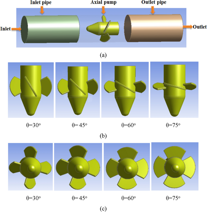
Analysis Of The Effect Of Various Impeller Blade Angles On Characteristic Of The Axial Pump With Pressure Fluctuations Based On Time And Frequency Domain Investigations Springerlink

Impeller Vane Model And Grid A Model Of Axial Flow Pump Impeller Download Scientific Diagram

Pdf Performance Analysis Of Axial Flow Mixing Impellers

Centrifugal Impeller Design Types And Uses
Axial Flow Pump Review

Useful Info On Specific Speed Suction Specific Speed
Axial Flow Pump Review
0 comments
Post a Comment